Selecting Accurate Flow Control Restrictors for Electrical Propulsion

ION Propulsion is the preferred option for a wide range of space missions.
Ion propulsion systems offer a more efficient use of fuel and electrical power as compared to other propulsion technologies. Therefore, ion thrusters are the preferred option for a wide range of space missions such as satellite station-keeping, orbit insertion, and deep space exploration. Spacecraft powered by ion thrusters can achieve incredibly high speeds—reaching up to 200,000 miles per hour. However, the trade-off is that ion thrust- ers generate low thrust when compared to alternatives such as chemical propulsion. To achieve the same overall change in momentum, they must operate reliably for longer durations, in some cases for many thousands of hours.
The gas feed system is one of the critical systems in ion propulsion. It controls the flow of a noble gas, such as xenon or krypton, to the inlet of the anode and cathode ports of the ion thruster. Flow through the anode is used to provide thrust; flow through the cathode is used to balance the charge emitted by the ion beam and to initialize and sustain the plasma discharge. It is critical to ensure the precise ratio of flow between the anode and cathode.
The cathode is one of the most complex aspects of thruster design, because it is fragile and difficult to operate. It is also critical to the stability of the thruster during start-up and to the efficiency of the system. Any excess flow through the cathode beyond that which is used to balance the charge, is simply lost.
It is no longer available to provide additional thrust, thereby reducing the efficiency and life of the system. One method of creating this precise flow ratio is employing precision calibrated flow orifices to meter the propellant into the thruster.
THE CHALLENGE: Controlling the flow ratio between anode and cathode ports in ION Propulsion
Generally, a single orifice metering element is the simplest and most accurate way to meter flow. However, the flow requirements of ion thrusters are typically extremely low and require very small orifice sizes; these are highly susceptible to contamination and less practical to manufacture using conventional production methods. As a result, alternate methods of restriction should be explored to produce the desired flow performance.
Propellant metering orifices represent critical components within a propellant feed system and play an important role in the efficiency of an ion thruster. When selecting a metering orifice or device, an engineer must consider several design parameters, including the following:
- Metered Flow Rate – The critical feature of a precision orifice is that it provides the optimal flow rate of propellant to the appropriate location. The properties of the gas, the entry and exit geometries, and the length and diameter of the orifice all impact flow rate. The propellant and target flow rate should be specified.
- Flow Rate Tolerance – In a mass production environment there will inevitably be some variation from orifice to orifice. A critical system requirement is an understanding of the way production tolerances of individual orifices influence the total tolerance. The tolerance stack up of multiple orifices in parallel can be described by the following equation:

The tolerance of the higher flow rate orifice, the anode, will have a greater impact than that of the cathode on the total flow tolerance and the resulting flow ratio. - Resistance to Debris and Contamination – The smaller an orifice, the more susceptible it becomes to clogging due to debris introduced during handling, manufacturing, or operation. It is important to know the minimum passage size of the metering device and whether any integral protection is required.
- Pressure Conditions – A propellant feed system typically operates through the use of a pressurized tank. As the propellant exits the tanks, any restrictions within the system—including tubing, plenums, sensors or other components—may impact the pressure at a specific point within the system. The upstream and downstream pressure conditions must be understood when selecting a precision orifice. As propellant is consumed, the pressure in the tank is reduced, so it is important to consider all potential pressure variations when specifying performance requirements. The orifice needs to withstand the full range of pressures for the life of the system.
- Temperature – As a spacecraft moves between the cold darkness of space into direct sunlight, the temperature changes drastically. Thermal management systems are used to control the temperature of the spacecraft. However, the mass flow controller is typically located as close to the thruster as possible, usually outside the spacecraft. Even a 20-degree temperature change can impact propellant flow rate due to changing fluid properties.
- Acceptance Testing Correlation – During the design phase, it is critical to test performance of the selected propellant under actual flight conditions. However, propellants are more costly and less easily attainable than more commonly used fluids (such as nitrogen) for acceptance testing in mass production. It is also impractical to acceptance test component hardware at every possible combination of system or environmental conditions. By correlating design requirements to an appropriate manufacturing acceptance test, cost and complexity can be reduced while verifying performance.
- Sonic vs. Subsonic Flow – It is important to pinpoint the transition from subsonic to sonic flow when developing a feed system, as this can have a significant impact on orifice performance. When an orifice is flowing under sonic conditions, mass flow rate is independent of the downstream pressure. This is preferable for a gas feed system, because it ensures consistent flow performance over a range of upstream pressures, regardless of fluctuations in backpressure.
- Envelope/Installation – The propulsion system typically incorporates a series of tubing and connections. Metering orifices can be installed into a manifold or connected in-line using a fitting or welded connection.
- Material – The material should be carefully selected to ensure it is compatible with the gas flowing through it, resistant to the environment it will be subjected to, and optimized for the chosen installation method. In addition, the selected material will impact the overall weight of the satellite or spacecraft. It is beneficial to keep the weight to a minimum, reducing thrust requirements during launch and operation.
- Cleanliness Requirements – It is important to determine the system or subsystem’s level of sensitivity to contamination. Doing so will further highlight the need for additional processing beyond standard levels of cleanliness available in a manufacturing environment and through normal cleaning procedures. Sensitive components or assemblies may need to be cleaned and packaged in a clean room environment. Parts are generally cleaned to meet specific particle cleanliness levels per an industry standard such as IEST-STD-CC1246.
THE SOLUTION
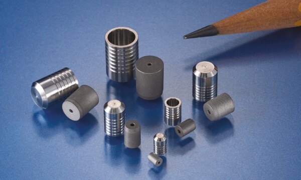
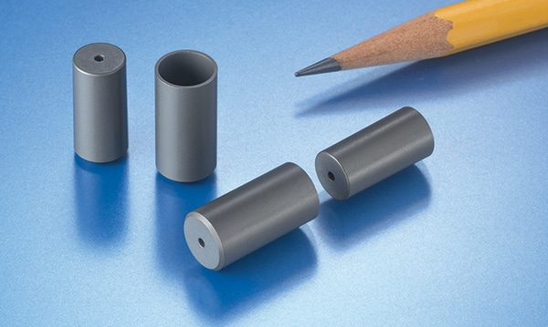
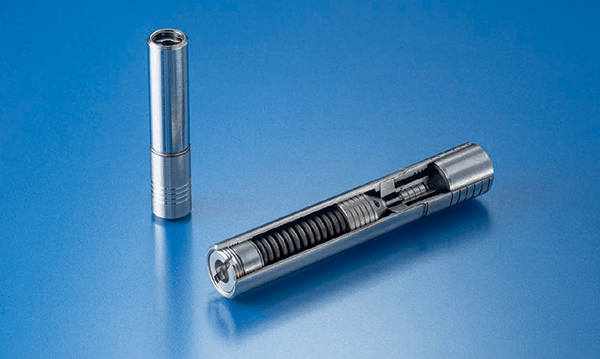
Lee Visco Jets and JEVAs offer an alternate solution: integrating a complex fluid passage with numerous orifices in series to create a multi-orifice restrictor in a miniature package. The combined effect of taking pressure drops across a series of orifices offers very high restrictions with a large minimum passage size. For example, a Lee Visco Jet can replace a single 0.0004″ orifice with an equivalent restriction that includes a minimum passage of 0.005″; this allows for a more reliable device that is much less susceptible to contamination. Even with the larger passage size, the Lee Visco Jet and JEVA are in a miniature, lightweight package: it is less than an inch long with integral safety screens on both sides of the metering element for additional protection.

Lee Visco Jet
The Lee Company 100% flow tests each multi-orifice restrictor, because accurate metering of the propellant is required for the anode and cathode feed lines. Acceptance testing may include flow testing using nitrogen at specific pressure drops to simplify the correlation to alternative noble gases. This will ensure the most reliable and accurate performance. The Lee Visco Jet can be customized with flow rate accuracies as low as +/-3%. With the cathode flow typically representing about 10% of total mass flow, this variation accounts for only about +/-0.3% of total mass flow rate.
Lee multi-orifice restrictors are constructed entirely from stainless steel to handle the extreme pressures and temperatures common in space systems. They are available in a variety of installation configurations to allow for design flexibility. The Lee Company developed a field-proven locking end that allows the component to be installed directly into a manifold. Utilizing this self-retaining feature eliminates the need for elastomeric seals and securely locks the component into place without any bypass leakage. Line mount configurations are also an option and may include special tube ends that can be welded directly in-line. The Lee Company has an on-site clean room facility capable of cleaning parts to meet specific customer cleanliness levels such as NAS 1638 or IEST-STD-CC1246.
ADDITIONAL POTENTIAL APPLICATIONS FOR LEE MULTI-ORIFICE RESTRICTORS
In addition to pedigree on satellite and spacecraft thrusters, Lee multi-orifice restrictors are operating in a wide range of space applications: launch vehicles, crew capsules, landers, on the International Space Station, and on spacesuits. These precision orifices:
- meter flow in fuel, purge, oxygen and environmental control systems
- dampen pressure pulses upstream of sensors
- control extend and retract rates of actuators used for thrust vector control or landing systems
Regardless of the application, Lee multi-orifice restrictors offer a reliable long-term solution where precision metering of liquids or gases is required.
FIELD PROVEN INNOVATION
The Lee Company has a long history of supplying devices for use in the space industry. They have been at the forefront of fluid control technology since 1948, supplying millions of innovative products worldwide from our state-of-the-art manufacturing facilities in Connecticut, USA. We, DenisDePloeg, helps The Lee Company transforming complex problems into deliverable solutions; we, together, do this through ongoing research, design, development, and commitment to quality and innovation. Our in-depth application knowledge enables us to collaborate with customers and provide personal technical support through a wide network of experienced sales engineers who are ready to address any challenge.